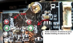
I replaced the B2 broken arm and cut all of the 7 wires and soldered them back on the right places.....except that black antenna wire which is just like a Sirius Radio antenna wire: a night mare to re solder and even worse with the hot-glue the manufacturers squeezed over the area. The youtube video shows how the person snipped the wires with a pair of scissors and used a big wedged solder point to resolder them all back....except the footage where it looks like they just resoldered the end of the snipped wires back on their globbed solder pad. I tried to use my Celestron hand-held microscope to see if I could locate where in hell they soldered that wire to. I could not tell. To the left of the blob is another labeled "antenna pad", which looks like it is bare from use. This black wire has braided shielding around a clear insulated center wire, does anyone know if the braided wire and the center wire are soldered together on that spot, or, if the braised wire solders to a spot and the center wire goes to another spot. The youtube video shows the person just soldering the wire back in place without doing anything but using that big solder tip to solder it back. I called holy stone and they would not tell me anything and do not help out with any suggestions to fix circuit boards. The circuit board is fine. And, if this wire is connected wrong, or shorted (like the video shows when they just soldered it back) will it burn the board up or just not communicate or drop from the sky......thank you for any help.
You are using an out of date browser. It may not display this or other websites correctly.
You should upgrade or use an alternative browser.
You should upgrade or use an alternative browser.
holy stone hs720 rear B2 antenna wire
- Thread starter winston smith
- Start date
h-elsner
Active member
I don't know the Holy Stone drone but I think all antennas follow the same rules. For better understanding, could you please post a picture from that antenna stuff? What ist the frequency that is used for that, 2.4GHz RC connection?
Usually those antennas are simple rod antennas. The black cable is a coaxial cable and must not shortend at the end. A shortcut may destroy the receiver.
However, it can be replaced by 2.4GHz WiFi antennas from an old notebook. I usually keep a lot of stuff before I draw away it.
Alternative there available is something like that:

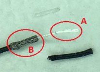
Some of those antennas have detuning sleeve added. The inner wire comes outside without touching the sleeve (hard to solder that, nearly impossible). The shiels must be soldered inside at the top of the sleeve. I have opened such a detuning sleeve just to see how it looks like:

br HE
Usually those antennas are simple rod antennas. The black cable is a coaxial cable and must not shortend at the end. A shortcut may destroy the receiver.
However, it can be replaced by 2.4GHz WiFi antennas from an old notebook. I usually keep a lot of stuff before I draw away it.
Alternative there available is something like that:
RC Ersatz Antenne 120mm 150mm 300mm 2,4GHz Empfänger FrSky Graupner Sanwa usw. | eBay
Finden Sie Top-Angebote für RC Ersatz Antenne 120mm 150mm 300mm 2,4GHz Empfänger FrSky Graupner Sanwa usw. bei eBay. Kostenlose Lieferung für viele Artikel!
www.ebay.de
Some of those antennas have detuning sleeve added. The inner wire comes outside without touching the sleeve (hard to solder that, nearly impossible). The shiels must be soldered inside at the top of the sleeve. I have opened such a detuning sleeve just to see how it looks like:
br HE
This black antenna wire comes thru the arm with the other 6 wires and takes a left turn and is soldered to the ESC (?) board on the edge. The video show a fast globby solder job by the worker; the other 6 wires go to the right and are easily soldered. I am going to gut this Holy S_hit HS720 drone and use this as a frame for a drone made with "common" parts. If Holy S wants to be a like apple computers and use proprietary boards and won't help you fix your stuff other things can be used.I don't know the Holy Stone drone but I think all antennas follow the same rules. For better understanding, could you please post a picture from that antenna stuff? What ist the frequency that is used for that, 2.4GHz RC connection?
Usually those antennas are simple rod antennas. The black cable is a coaxial cable and must not shortend at the end. A shortcut may destroy the receiver.
However, it can be replaced by 2.4GHz WiFi antennas from an old notebook. I usually keep a lot of stuff before I draw away it.
Alternative there available is something like that:
RC Ersatz Antenne 120mm 150mm 300mm 2,4GHz Empfänger FrSky Graupner Sanwa usw. | eBay
Finden Sie Top-Angebote für RC Ersatz Antenne 120mm 150mm 300mm 2,4GHz Empfänger FrSky Graupner Sanwa usw. bei eBay. Kostenlose Lieferung für viele Artikel!www.ebay.de
Some of those antennas have detuning sleeve added. The inner wire comes outside without touching the sleeve (hard to solder that, nearly impossible). The shiels must be soldered inside at the top of the sleeve. I have opened such a detuning sleeve just to see how it looks like:
View attachment 144
br HE

jdw3rd
Active member
jdw3rd
Active member
When I had to replace my armatures this corner of the board was covered in a brown colored clay/epoxy which I had to scrape off to find the connections.
jdw3rd
Active member
The center conductor and the shielding ARE NOT soldered to the same pad - the shielding is grounded.I replaced the B2 broken arm and cut all of the 7 wires and soldered them back on the right places.....except that black antenna wire which is just like a Sirius Radio antenna wire: a night mare to re solder and even worse with the hot-glue the manufacturers squeezed over the area. The youtube video shows how the person snipped the wires with a pair of scissors and used a big wedged solder point to resolder them all back....except the footage where it looks like they just resoldered the end of the snipped wires back on their globbed solder pad. I tried to use my Celestron hand-held microscope to see if I could locate where in hell they soldered that wire to. I could not tell. To the left of the blob is another labeled "antenna pad", which looks like it is bare from use. This black wire has braided shielding around a clear insulated center wire, does anyone know if the braided wire and the center wire are soldered together on that spot, or, if the braised wire solders to a spot and the center wire goes to another spot. The youtube video shows the person just soldering the wire back in place without doing anything but using that big solder tip to solder it back. I called holy stone and they would not tell me anything and do not help out with any suggestions to fix circuit boards. The circuit board is fine. And, if this wire is connected wrong, or shorted (like the video shows when they just soldered it back) will it burn the board up or just not communicate or drop from the sky......thank you for any help.
Attachments

BlueAero91
Member
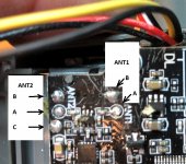
Is the integrity of the clear external wire ("A" in the pic ANT02.jpg) critical to the ability of the quadcopter to send and receive the WIFI signal and/or commands from the controller? Mine was partially severed in a crash and, although I did a ground check to make sure my quadcopter was still able to do so and it appears to be communicating adequately. However, now I'm concerned about actually flying it any distance away that might result in a loss of signal. Any assistance appreciated. Tks.The center conductor and the shielding ARE NOT soldered to the same pad - the shielding is grounded.
Attachments
h-elsner
Active member
The easiest kint of antenna is this coaxial antenna that looks like the picture above. The legth of the wire depends on frequency and its wave length lambda. B as well as A should have the length of lambda/4.
The wire should have 31mm lenght for the 2.4GHz band. Sometimes it is shorter for optimal impedancy depending on construction, but to optimize it we usually don't have measurement equipment. 31mm is a very good approach.
br HE
The wire should have 31mm lenght for the 2.4GHz band. Sometimes it is shorter for optimal impedancy depending on construction, but to optimize it we usually don't have measurement equipment. 31mm is a very good approach.
br HE
BlueAero91
Member
Thanks for the reply, H. So, if I may summarize your remarks, the damaged (and shortened) antenna is less than optimized. The shorter it is, the less effective it is at receiving and sending signals. Correct?The easiest kint of antenna is this coaxial antenna that looks like the picture above. The legth of the wire depends on frequency and its wave length lambda. B as well as A should have the length of lambda/4.
The wire should have 31mm lenght for the 2.4GHz band. Sometimes it is shorter for optimal impedancy depending on construction, but to optimize it we usually don't have measurement equipment. 31mm is a very good approach.
br HE
h-elsner
Active member
Yes, this correct. And the same is valid if it is longer than lambla/4. The length shall match the wave length and wave length depends on frequency that is used for connection.The shorter it is, the less effective it is at receiving and sending signals. Correct?
br HE
BlueAero91
Member
That explains a lot. Thank you, sir!Yes, this correct. And the same is valid if it is longer than lambla/4. The length shall match the wave length and wave length depends on frequency that is used for connection.
br HE
I have a question. There is Ant 1 and Ant 2 in the above pictures. Now the black wire that comes with the replacement arm is connected to Ant 2. This can be either 2.4ghz for the controller or 5ghz for wifi. So have you established which antenna is on Ant 2?